We covered the cameras in Part 1: Cameras and now we're moving on to covering the eye mechanism which is constructed from 3D printed parts.
Whilst following this; please refer to Eye Mechanism Assembly on the InMoov website. Particularly as the part versions may have been updated if you're reading this a while after it's been published.
This is the section of InMoov that we've put together:
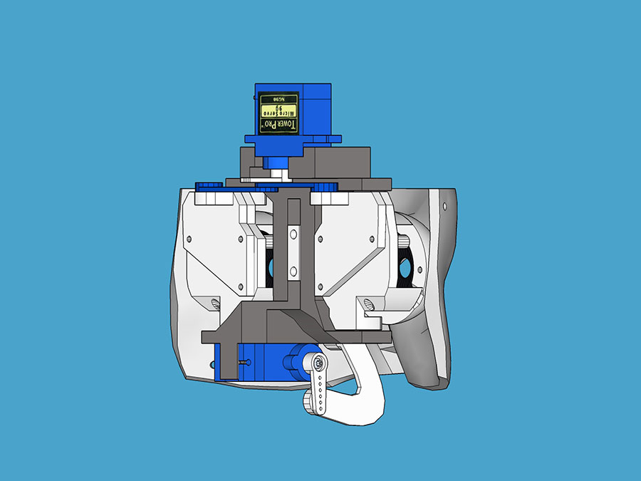
The above image was exported from the awesome SketchUp file: 3d Inmoov V1 SketchUp by Mindless.
Parts List
This list is taken straight from the InMoov website but updated with the correct filenames (at time of writing).
You will need to print all these parts at a good resolution:
- 2x EyeBallFullV2
- EyeHingeCurveV1
- EyeHingeV2
- EyeHolderV1
- EyePlateLeftV1
- EyePlateRightV1
- EyeSupportV5
- EyeTo NoseV5
We're using the Hercules HD Twist (see: Part 1: Cameras) so we printed:
- EyeBallSupportHerculeLeftV2
- EyeBallSupportHerculeRightV2
But if you're using the LifeCam 3000 you'll need:
- EyeBallSupportLifeCamHDLeftV1
- EyeBallSupportLifeCamHDRightV1
You need two Mini Servos for the eye movement:
- 2x Corona DS929HV (or similar)
ABS or PLA or?
Gael notes that he's using ABS but others have used PLA so I guess it's up to you and your type of printer when it comes to what you're going to use.
We're using the Flashforge Creator Pro 2016 so we have many options open to us and we'll experiment with some more exotic filament material at some point in this build process.
Generally ABS is stronger and better suited for load bearing or more mechanical printing so we're printing primarily in ABS with a few exceptions.
We printed the outer head parts; and plan to print all the main, white aesthetic parts in PLA as it gives better layer resolution and we're not bothering with smoothing things out with acetone on this version.
Printing
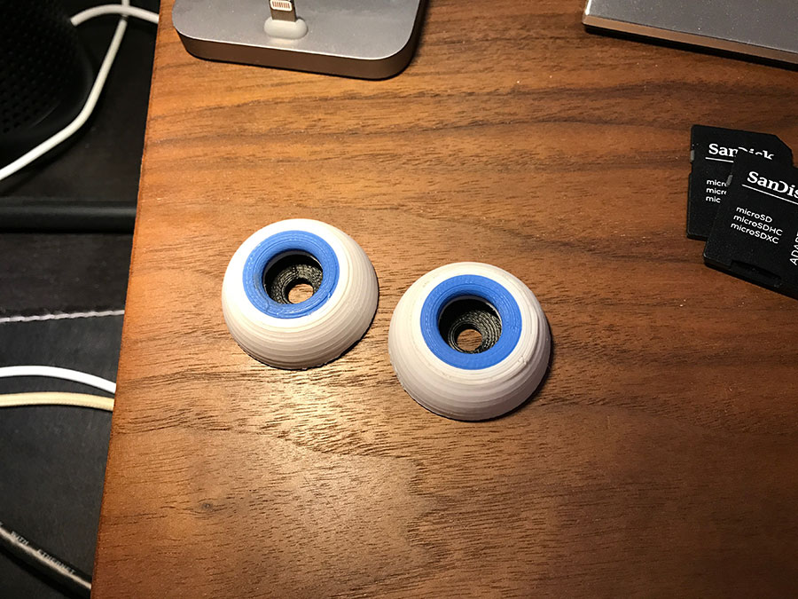
We sliced up "2xEyeBallFullV2" in order to print the parts in different colours rather than painting them.
The large, main "eyeball" section and smaller insert were printed in white PLA, the "iris" was printed in pale blue PLA and the back section - surrounding the camera and becoming the "pupil" was printed in black PLA.
We had to file and sand the parts a little in order to fit them together - a tight push-fit which didn't require any adhesive.
We then printed all of the remaining parts in black ABS apart from "EyeTo NoseV5".
We printed "EyeTo NoseV5" in PLA and increased the fill to make it stronger as our white head parts are printed in PLA and it made sense (to us) to keep these plastics the same when using adhesive.
Assembly
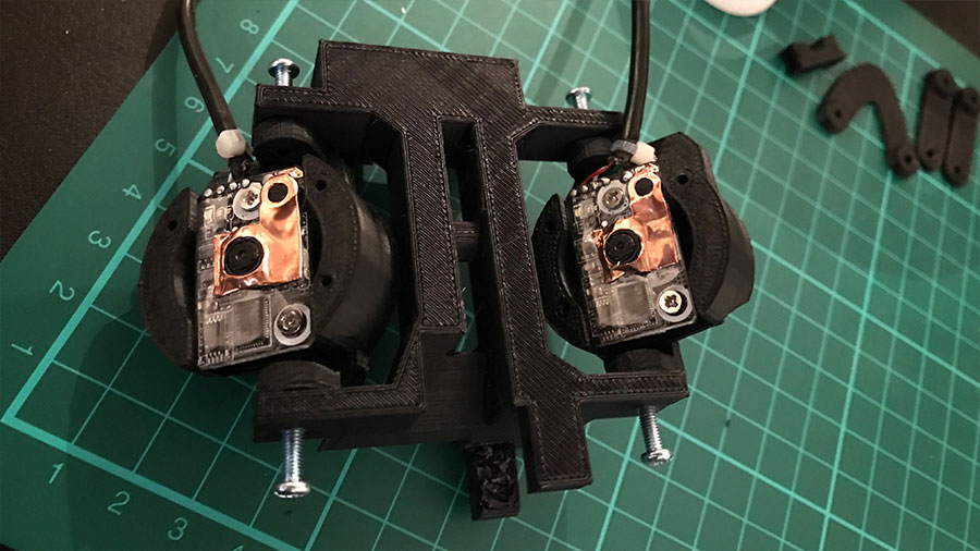
As noted in Part 1: Cameras; we attached the Hercules cameras to "EyeBallSupportHerculeLeftV2" and "EyeBallSupportHerculeRightV2" using the silver screws from the Hercules plastic enclosure.
We used a 2.5mm drill and then an M3 tap in "EyeSupportV5" where the screws mount to "EyeBallSupportHerculeLeftV2" and "EyeBallSupportHerculeRightV2".
We then fitted the camera parts to "EyeSupportV5" making sure that we attached them the correct way around (note that the vertical line that flows to the servo mount that protrudes is the bottom of the piece, as shown in this image).
We attached "EyeTo NoseV5" to the "EyeSupportV5" with the "EyeHolderV1".
Test fitting the parts to make sure all is well:
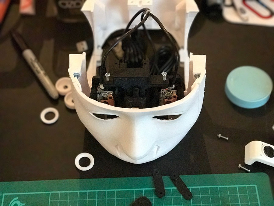
Test fitting the parts before attaching the eyeballs; InMoov looks a little sinister here:
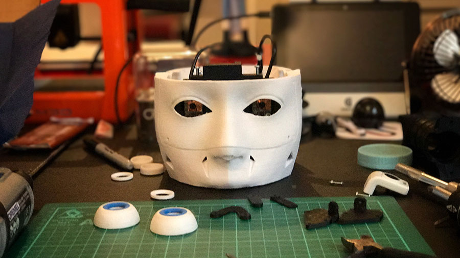
Once assembled and checked to ensure the eyes move freely you can attach the eyeballs and fit the servos.
Servos
Two servos are required for the eye mechanism; one for moving the eyes up and down and one for moving them side to side.
We used a pair of Corona DS929HV from HobbyKing as recommended.
InMoov - Part 3
From here; we'll assemble the head and neck in our next blog post.
- Part 3: Head and Neck (coming soon)
InMoov - Index
If you haven't read about our build from the beginning; be sure to check the initial blog post/index: